SC16IS7XX dual UART driver
The MH5 HAT uses an SC16IS762 chip to provide 2 semi-duplex TTL Dynamixel channels for communicating with the servos and sensors.
Why choosing SC16IS762 chip
While there are many options for providing a Dynamixel compliant solution for Raspberry Pi, they can be grouped in three main categories:
using the built-in serial ports
using USB to UART adapters
using SPI to UART adapters
In order to understand the needs of a Dynamixel compliant bus, you need to be aware of the specifications of this interface. The detail about the physical definition of this interface are presented in the Robotis eManual. Specifically the devices MH5 use conform to a semi-duplex TTL serial communication that means the data bus is shared between sending and receiving and the master (the communication controller) is responsible for switching its mode between read and write to avoid cross-talking and echo. The following diagram, extracted from the eManual describes a possible implementation of this duplex control:
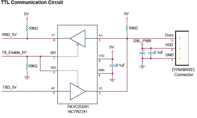
TTL Communication Circuit Example (source: Robotis eManual)
The first option is very limited due to the following elements:
There is only one UART available on the Raspberry PI board and typically this is used for console access to debug the system in case the other modes of access (WiFi, Ethernet) are failing. The MH5 HAT includes a CP2104 USB to UART convertor that is connected to this UART port and is providing exactly this type of functionality
The duplex control described above will have to be implemented using a GPIO pin from Raspberry Pi and, while this is achievable, the fact that Raspberry Pi uses a Linux system that is inherently non-real-time creates complications in timing of the switching of this GPIO and then read / write of data over the RX / TX lines of the UART, especially at high speeds (1Mbs or higher).
The second option is used by the majority of implementations provided by Robotis, including the old USB2Dynamixel, the newer U2D2 as well as the more complex Open CR and Open CM. In some previous incarnations of the MH robot (MH2 for instance) the controller board also used an USB to UART converter (FTDI 4232HL) that provided 4 independent serial busses. This is an attractive option with the following advantages:
Possibility to produce 2 or 4 UART channels (depending on the chip used) from one USB bus
Possibility to leverage the hardware control flow from RS485 protocol to drive the semi-duplex circuits above. Practically, once the circuits are configured in RS485 mode, each port can use the TXDEN pin to control in hardware the communication direction without any more involvement from the main controller.
Ability to handle communication speeds up to 12Mbs per channel. The typical Dynamixel devices (specifically the ones we target for the robot designs in MH group) support communication speeds up to 4.5Mbs, so the capabilities of the chip more than cover the communication needs.
While this is an attractive option there are also a few drawbacks:
On the Raspberry Pi platforms the USB ports are provided with standard A Ports connectors (the chips use USB 2.0 as they don’t need ultra high speed provided by USB 3.0) and this would require USB cables between the Pi and the add-on board. While this might not seem much, for small robots like MH5 the added bulk and weight off the cables is a problem (a typical USB cable connector is roughly as long as 1/2 of a Raspberry board). It is an element that must not be taken easily in consideration. Using other board (like the newer Compute Module 4) might bypass this restriction as the USB ports (2.0) are provided as pins on the expansion sockets.
USB device communication include a latency that is not a problem for high volume / small number of packages exchange but becomes a limiting factor for communication protocol like Dynamixel that uses small packages and the exchange read / write follows quick successions. While this latency can be reduced to 1ms (between packages exchanges) it still creates a bottleneck when communicating at high speeds and when more than 6 devices are connected on a single bus (which is very possible for a robot with over 20 DOF).
Note
The latency timer constraints are also built in the DynamixelSDK code that is provided as an Open-Source by Robotis. In case of communication errors the library uses the default latency (16ms) to determine the timeout when exchanging packets on the serial bus. While this might impact negatively the performance only when there are errors, the fact that the framework will wait for 16ms+ before it decides there was a problem might reduce significantly the communication speed. Changing this parameter to a significantly lower value (even less than 1ms for interfaces that do not exhibit such latency like the SPI below) might significantly improve the performance of the communication and allow for faster synchronization cycles with the servos.
Which leaves us with the third option the SPI to UART adapters. There are a few advantages complementing the disadvantages listed for the previous options:
It is convenient to connect such a chip directly to the SPI pins provided by Raspberry Pi without added bulk like the USB connections.
There are options with 2 and 4 UARTs form the same SPI connection.
Chips might support up to 4Mbs per bus, although the particular limits are defined by the actual SPI constraints (see bellow more details)
Chips will generally support hardware control which means that all direction switching will be handled in hardware and the main controller will simply read / write as a normal serial bus.
The disadvantages for this solution are:
While the Raspberry Pi includes two SPI buses, SPI0 and SPI1, the later one is disabled due to the use of I2S interface for the sound chip WM8960. That leaves us with only one interface SPI0 that will have to be shared with the TFT screen. This might not be really a big issue (the screen will be configured with 40Mbs communication speed and the SC16IS762 at 15Mbs which is comfortable bellow the rated communication allowed over SPI) certain conflicts might arise between the two that would impact the actual transfer speeds.
Typically the SPI0 is provided by the standard Device Tree for Raspberry Pi with 2 Chip Enable pins (GPIO8-CE0, GPIO7-CE1) if we plan to use a TFT with touch controller (currently the display does not use touch)that also connects over SPI we will need to provide an overlay that extends these to a third CE pin see here.
There is a standard driver for SC16IS7XX chips in the linux kernel and is subject to maintenance by the Raspberry Pi community. I have found many performance related problems that had to be addressed with the actions listed bellow. Once the kernel will have these issues solved some of these actions might not be necessary.